Industry & additive manufacturing
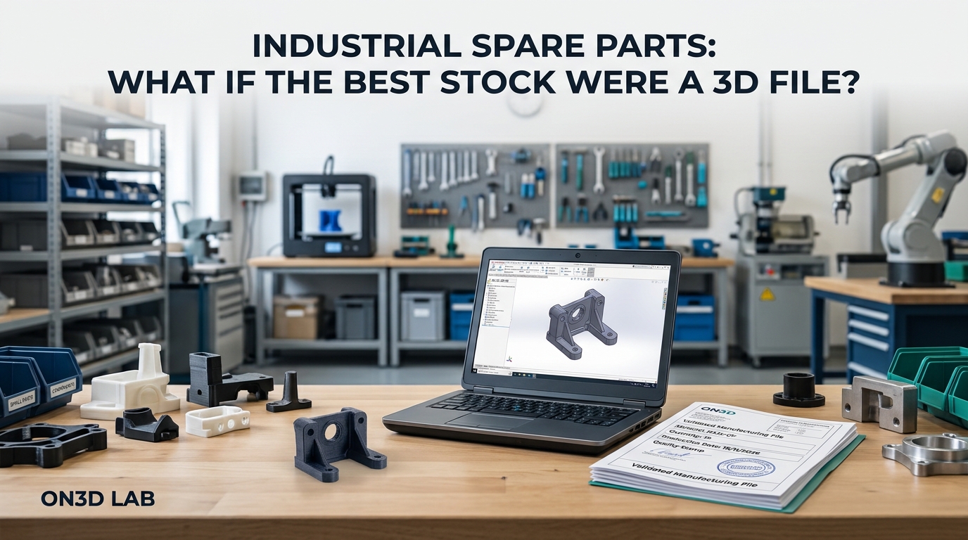
Industrial spare parts: what if the best stock were a 3D file?
Some plastic parts are better retained as validated manufacturing dossiers than as dormant stock. Methods, examples and limitations.
Learn how 3D scanning, CAD reconstruction and 3D printing can help reproduce certain industrial plastic spare parts that are no longer available.
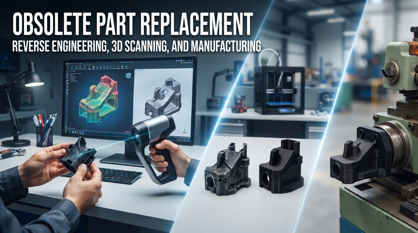
A machine still works, but a small plastic component breaks. The manufacturer no longer supplies it, the drawing has been lost, or the lead time is disproportionate. In some cases, reverse engineering makes it possible to start with the physical part, create a usable CAD model, manufacture a replacement and check that it fits.
The shortcut “scan and print” is misleading, however. Between measurement and manufacturing, the team must understand the part's function, reconstruct important features, choose a material and inspect the result. These steps determine whether the solution will work.
A cover, guide, handle, sensor bracket or interface component can stop a machine even when the rest of the equipment is serviceable. If drawings and 3D files are unavailable, the part kept on site becomes the main source of information.
Reverse engineering turns that object into a usable digital definition. The goal is not always an exact copy: a worn or distorted part may require reconstruction of its original geometry and an adjustment that remains compatible with the machine.
This approach is most useful for a maintenance part, prototype, adaptation or small production run. It can also prepare a later move to a different manufacturing process if volumes increase.
A 3D scanner captures visible surfaces. Its measurements are usually processed into a point cloud and then a mesh made of triangles. The mesh describes the observed shape, including any defects.
A parametric CAD model instead describes features that can be understood and changed: planes, axes, diameters, holes, wall thicknesses and radii. It can, for example, correct the spacing between two holes or reinforce a mounting point without editing thousands of triangles.
Autodesk Fusion's documentation shows how mesh sections can be used to create sketches and then reconstruct parametric surfaces and solids. Specialist software such as Geomagic Design X also provides tools for processing scans and rebuilding CAD geometry.
Key point: a mesh records the object as observed. A CAD model defines the part to be manufactured.
Existing part → functional analysis → measurement or scanning → mesh → CAD reconstruction → adaptation → material and process selection → prototype → inspection → archiving.
First, identify the interfaces: bearing surfaces, fasteners, axes, clips, cable routes, seals and connections with neighbouring components. An outside curve may be secondary, while the spacing between two holes may determine whether the whole assembly fits.
Service conditions matter as much as dimensions: heat, vibration, impacts, moisture, sunlight, oils, chemicals and frequency of use. They guide both reconstruction and the choice of plastic.
A drilled plate or a simple spacer can sometimes be rebuilt faster with calipers and a few targeted measurements. Scanning is useful when the part has curves, ribs, transitions or surfaces that are difficult to measure directly. The two methods can work together: scanning for the overall shape and direct measurement for functional dimensions.
A scanner's stated accuracy does not describe the accuracy of the finished part. For example, Creaform specifies accuracy of up to 0.030 mm for its HandySCAN 3D PRO. That figure applies to the measuring system under its stated conditions. It does not guarantee the accuracy of a printed part or describe the capabilities of another workshop.
Final quality depends on the entire chain: the condition of the original part, data capture, mesh processing, CAD reconstruction, manufacturing process, material, deformation during production and final inspection.
An old part may be cracked, worn, compressed around a screw or warped by heat. Faithfully copying that geometry could reproduce the defect.
Instead, the team tries to recover a consistent geometry from intact areas, symmetry, mechanical axes and adjacent components. Critical dimensions are defined and checked separately. Any design change intended to improve the part must remain compatible with the equipment.
The first part can serve as a prototype: check its overall size, fasteners, clearances and fit before deciding on final production. Select the material and process according to the actual loads and environment. A printable part is not automatically fit for service.
Safety-related components, heavily loaded parts and parts subject to certification need appropriate engineering validation. A fit check alone is insufficient.
Imagine an old plastic cover with cracks around two mounting points. A scan can capture its outside shape and curves that are difficult to measure. The damaged mounting areas should not simply be copied.
After investigating possible causes of the cracks, the mounting features are rebuilt in CAD using their axes and the machine's interfaces. If space allows, a larger radius or a locally thicker section can be considered. A prototype is then used to check the fit and refine the model.
The outcome is more than a reproduction: it is a digital definition that can be checked and reused.
The first manufactured part replaces the broken one. The CAD file avoids repeating the full reverse engineering process next time. It can be corrected, adapted to another version of the machine or used as a basis for tooling.
A useful technical record should include:
Together, these records form a digital stock of spare parts. They do not eliminate the need to validate each new production run, but they reduce the work of reconstructing the part.
3D printing is particularly relevant when only a few parts are needed and a mould or conventional tooling would be disproportionate. It can speed up prototyping, validation and some maintenance production.
ISO/ASTM 52900:2021, confirmed in 2025, defines the general terminology of additive manufacturing. On a real project, the manufacturing file is only one step. Stiffness, heat resistance, flexibility, chemical exposure, build orientation and long-term behaviour also need consideration.
The best choice is not simply “the strongest plastic”. It is a combination of geometry, material, process and inspection suited to the actual use.
| Situation | Value of reverse engineering |
|---|---|
| Manufacturer has discontinued the part or no drawing is available | High if a sample or its interfaces can still be accessed |
| Low quantity or a prototype is needed | Often high |
| Complex shape that is hard to measure | Scanning may save time |
| Simple part that is easy to measure | Direct measurement may be enough |
| Worn or distorted part | Possible, with reconstruction of functional areas |
| Very large production run | Useful for prototyping; another process may suit production better |
| Safety-related or regulated component | Specific engineering assessment, tests and requirements are essential |
A scanner generally captures only accessible surfaces. Cavities, hidden areas and internal features require other measurements or inspection of neighbouring parts. If the original material is unknown, choosing a replacement polymer also requires further analysis.
Success is measured by how the new part performs, not only by visual similarity. Lead time, total cost and the required level of validation matter too. For a simple part already available at a reasonable price, reverse engineering may not be the best option.
For a workshop or manufacturer operating older equipment, local access to measurement, CAD and manufacturing capabilities can make it easier to assess an unavailable part. The same method can support a prototype, an adaptation or a small pre-production run before moving to a more suitable production process.
The value lies in turning a repair need into reusable technical data while checking that the new part truly meets its intended use.
When a spare part cannot be found, the first question is not simply “Can we print it?”. The team must establish whether it can recover the part's function, reconstruct reliable geometry and choose an appropriate manufacturing method.
At ON3D Lab, an assessment can start with the existing part and the equipment it fits: feasibility analysis, 3D modelling or reconstruction, plastic selection, prototyping and inspection. If you have a broken part with no 3D file, an initial assessment can determine whether reverse engineering is a sensible route.
Some plastic parts are better retained as validated manufacturing dossiers than as dormant stock. Methods, examples and limitations.

A practical guide to selecting an FDM material for your part's actual exposure to heat, UV, impacts, friction, moisture and cost constraints.
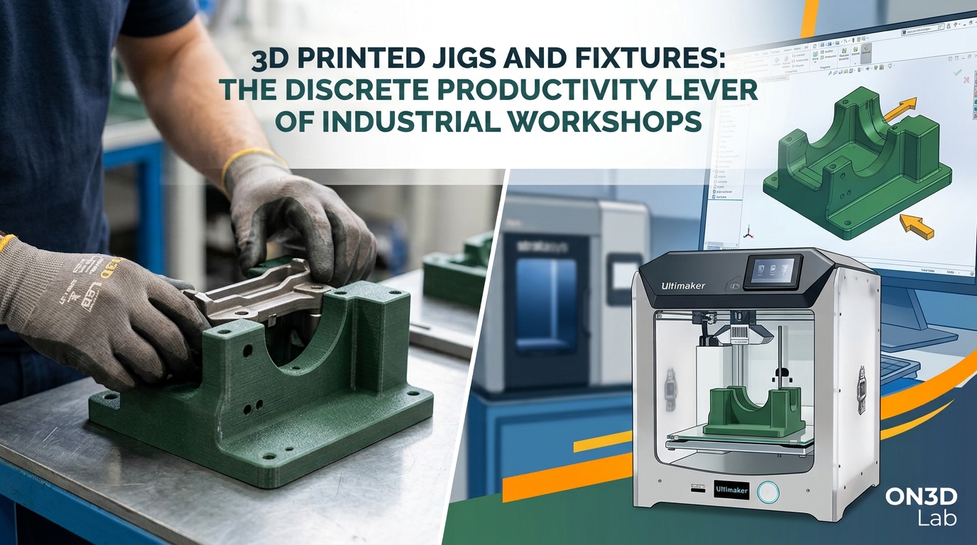
A well-designed plastic tool can make positioning, assembly and inspection easier. Explore applications, limitations and a practical method for assessing workshop benefits.