Materials
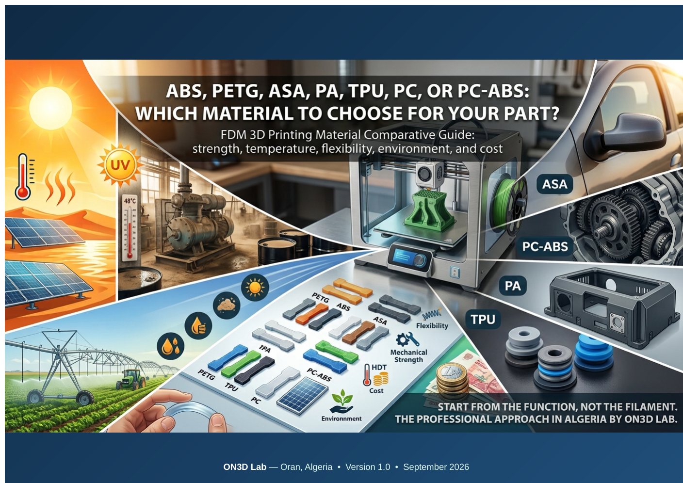
ABS, PETG, ASA, PA, TPU, PC or PC-ABS: Which material should you choose for your part?
A practical guide to selecting an FDM material for your part's actual exposure to heat, UV, impacts, friction, moisture and cost constraints.
Explore how 3D-printed jigs and fixtures can improve assembly and inspection in Algerian workshops: applications, materials, limitations and cost benefits.
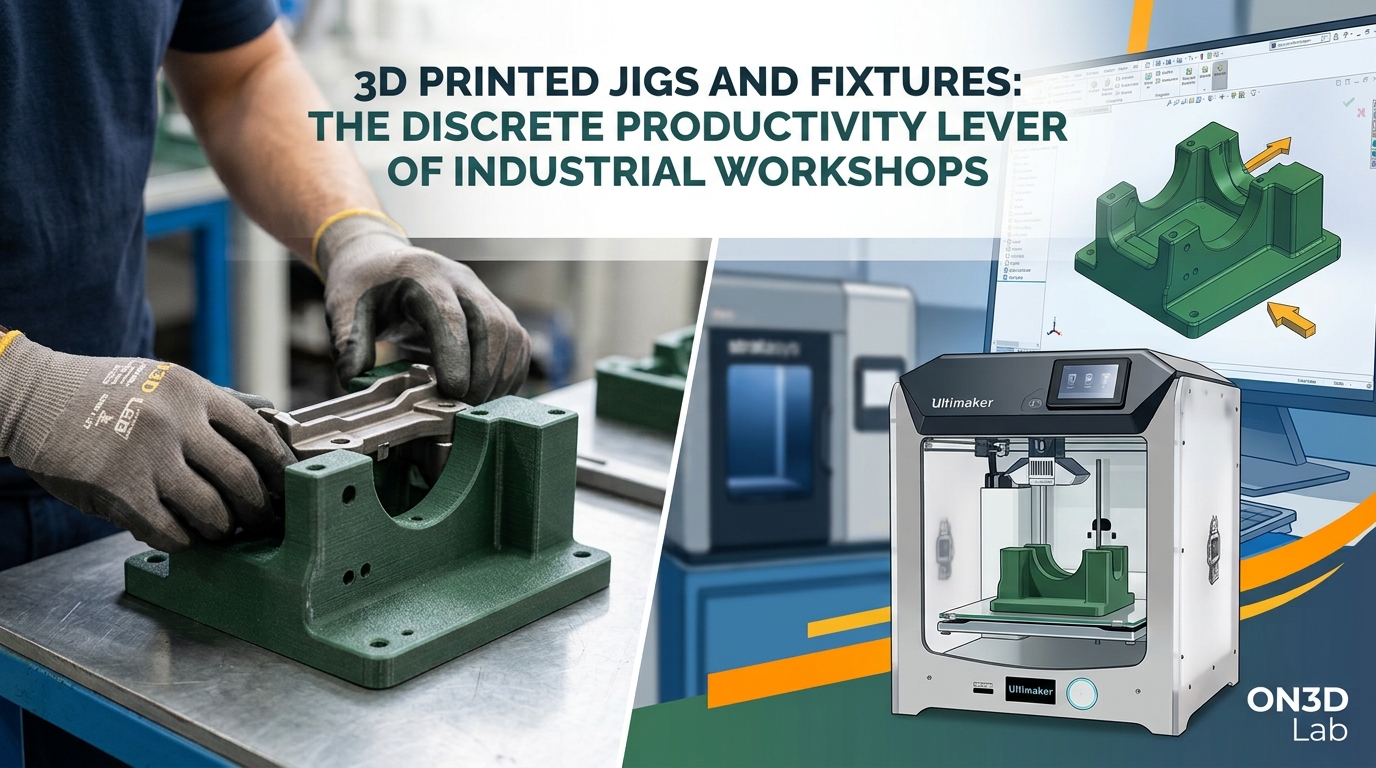
Innovation on the shop floor does not always mean a new machine. Sometimes it is simply a tool designed around the operator’s task.
A few seconds lost positioning a part, an unstable assembly setup or an inspection that is difficult to repeat can become real production problems. Yet these issues do not always justify designing and machining a custom metal tool.
3D-printed jigs, fixtures and manufacturing aids offer another approach: design a plastic solution for the workstation, test it, and refine it through actual use. The value is not just the price of the tool. It lies in fewer handling steps, better repeatability and easier adaptation when the product changes.
When a company sets out to improve productivity, it often thinks first about a new machine, automation or software. But time is also lost before and after the main operation: positioning a housing, holding a part during assembly, checking a hole spacing, orienting a component or arranging items in the correct order.
An experienced operator may compensate for these difficulties. The process can nevertheless become less repeatable when a new colleague joins the team or a production run switches to another part number.
A simple tool designed for a specific operation can make the correct movement more natural. It does not replace expertise: it helps make that expertise repeatable.
| Tool | Main purpose | Example application |
|---|---|---|
| Positioning jig | Establish where a part or item should be placed | Repeatedly position a label or connector |
| Holding or assembly fixture | Stabilise a part during an operation | Hold a housing during an assembly step |
| Operation guide | Guide an operation using defined reference features | Guide a repeatable operation, with reinforced wear areas where needed |
| Inspection gauge | Check a defined characteristic | Quickly check whether a geometry passes or fails a functional limit |
| Kitting tray | Present components in an organised layout | Prepare an assembly kit and reduce component mix-ups |
These categories can overlap. The important point is to define precisely which operation the tool must make more reliable. Stratasys and UltiMaker document industrial applications ranging from holding and alignment to inspection devices and ergonomic manufacturing aids 12.
A plastic jig made by fused deposition modelling or fused filament fabrication (FDM/FFF) can be produced directly from a 3D model, without an injection mould. This is particularly useful for a one-off tool, a small batch, a pre-production run or a workstation that changes regularly 12.
The geometry can follow the shape of the part being held. Visual references, component pockets, handholds and contact areas can be incorporated into the design 12.
The first tool is not necessarily the final version. After testing at the workstation, it may make sense to change the height of a stop, enlarge a clearance, modify a handle or make a wear surface replaceable. A well-organised CAD model makes these changes easier 12.
The tool can be archived with its reference, revision, material and inspection criteria. When it wears out or another workshop needs a copy, these records make it possible to prepare a replacement without starting from scratch.
1. Electronics and enclosure assembly. A plastic fixture can hold a housing in a stable orientation while preserving access to its fastening points. It can also provide pockets for small components and help prevent assembly mix-ups. When exposed electronic boards are involved, electrostatic discharge requirements (ESD) must be assessed: a standard FDM plastic is not automatically static-dissipative 26.
2. Packaging and labelling. A positioning jig can help place a label, identification plate or accessory consistently on packaging or products. It is a useful starting point because the loads can be modest and the result is easy to observe.
3. Maintenance and short production runs. A dedicated fixture can stabilise a cover, housing or small non-critical part during inspection or assembly. Where individual surfaces face heavier demands, a hybrid solution may be appropriate: a plastic body with standard metal components only at the interfaces that need them 16.
4. Quick dimensional screening. A gauge can help an operator sort parts against a specific functional criterion. It does not replace a calibrated measuring instrument or an appropriate metrology procedure. Its purpose is to make an already validated, repetitive check simpler and more consistent 3.
These are potential applications for businesses in Algeria, including packaging, electronics, maintenance and industrial equipment. They are examples of possible uses, not projects claimed as ON3D Lab references.
Stratasys reports that Valeo used an ASA-printed go/no-go fixture for an automotive pipe. Inspection time fell from 25 minutes to 20 seconds per pipe, a 98.7% reduction. Fixture lead time was 2 weeks rather than 12 for the machined alternative 3.
These are results from one specific case, not a performance promise for ON3D Lab. Their wider lesson is to assess the operation time saved, rather than just the material cost of the tool.
Before modelling, establish the important geometric references, the loads, the expected number of cycles, the operating environment and how the operator will handle the tool. A part that simply fits another part does not, by itself, guarantee repeatable positioning 1.
An FDM part is built in layers. Its mechanical behaviour can vary with build orientation; loads that place unfavourable demands on interlayer bonding require particular attention. Orientation should therefore be selected around the loads and functional surfaces, not solely to minimise printing time 4.
The choice is not simply the material with a reputation for being the strongest. Temperature, stiffness, vibration, abrasion, humidity, chemical exposure and the duration of loading all need to be considered.
| Potential material | Possible tooling application | Main point to assess |
|---|---|---|
| PETG | Assembly aids and moderately loaded fixtures | Deformation under sustained load and heat |
| ABS / PC-ABS | Functional tooling for indoor environments | Print quality, impact, temperature and chemical compatibility |
| ASA | Tools that may be exposed to outdoor light | Mechanical and dimensional validation |
| PA (nylon) | Parts subject to friction or repeated loading, depending on formulation | Moisture absorption, dimensional stability and processing conditions |
| PC | Some fixtures requiring greater stiffness or thermal performance | Processing requirements and geometry validation |
| TPU | Contact pads, surface protection and compliant interfaces | Dimensional stability under load; chemical compatibility of the specific grade |
This table is intended to guide a feasibility review, not to qualify a material for every application. The datasheet for the actual grade, the design and practical testing remain decisive. Manufacturer application guides support this function-led approach 12.
The main body can remain 3D-printed plastic while standard components—threaded inserts, bushings, pins or fasteners—provide the functions that require better wear resistance or frequent disassembly. This does not mean that a 3D-printing workshop manufactures metal. It is a hybrid design combining custom plastic geometry with off-the-shelf components 16.
Checks should cover functional dimensions, stability, clearances, ergonomics, repeated loading and the absence of damage to the parts being handled. More sensitive functions require a documented validation protocol.
ISO/ASTM 52920:2023 sets out qualification and quality-related requirements for industrial additive manufacturing processes and production sites. It can provide a reference for organising production, but reading its summary is not enough to claim compliance 5.
A fixture that meets its dimensions on delivery may behave differently after weeks of sustained loading, heat or repeated handling. Polymers can exhibit creep, meaning gradual deformation under a sustained load; contact areas can wear and fasteners can loosen.
Formlabs highlights sustained loading and heavily worn interfaces in its tooling guidance. That guidance concerns SLA resin parts: it helps identify issues to investigate, but does not qualify the performance of an FDM material 6.
A printed tool is therefore not automatically suitable for very high holding loads, excessive temperatures, safety-critical use or demanding dimensional requirements that cannot be verified and maintained. A metal tool, a hybrid design or a different manufacturing process may be preferable.
The useful indicator is not only the manufacturing price. Compare the total cost with the benefit at the workstation.
Total tooling cost: design and modelling + manufacturing + standard components + validation trials + maintenance and potential replacements.
Potential benefits: shorter cycle times + less rework + fewer positioning errors + less waiting for tooling + easier adaptation to changes in part number.
To make the decision objective, measure the average operation time before and after introducing a prototype, over a representative number of cycles. Also record defects and rework. Calculate the net benefit from these observations rather than assuming a savings percentage in advance.
A cheap jig that slows the operator down is a poor investment. Conversely, a more developed custom fixture may be worthwhile if it makes a highly repetitive workstation more reliable.
The best starting point is not the most complicated part in the factory. It is a repetitive, observable operation with low safety criticality.
This approach can suit a maintenance workshop in Oran, an assembly operation, a packaging manufacturer or an electronics SME elsewhere in Algeria.
Industrial 3D printing does not have to replace a production line to be useful. It can simply provide the missing tool between the machine, the part and the operator.
Positioning jigs, assembly fixtures, kitting trays and inspection gauges are all applications where customisation and easy revision may make a difference. Each tool must still be treated as a production component, with defined requirements, a suitable material and validation proportionate to the risks.
At ON3D Lab, we support the design and manufacture of custom plastic parts and tooling for prototyping and production. Is a repetitive operation difficult to make reliable? A workstation photo, sketch or description of the constraints is a useful starting point for assessing a suitable fixture.
Discuss your tooling project with ON3D Lab
[1] Stratasys — FDM Jigs, Fixtures and Manufacturing Tools. Industrial application guide.
[2] UltiMaker — 3D printing jigs and fixtures: Revolutionizing manufacturing efficiency, 21 July 2025.
[3] Stratasys — Valeo Streamlines Quality Inspection with 3D Printed Fixtures. Manufacturer case study; results apply to the reported application.
[4] Stratasys — Additive Manufacturing Simulation for FDM Parts, 30 June 2026. Build orientation, toolpaths and mechanical behaviour.
[5] ISO — ISO/ASTM 52920:2023 — Requirements for industrial additive manufacturing processes and production sites, June 2023.
[6] Formlabs — Jigs, fixtures, and manufacturing aids. Design guidance for SLA resin tooling; not an FDM material qualification.
A practical guide to selecting an FDM material for your part's actual exposure to heat, UV, impacts, friction, moisture and cost constraints.
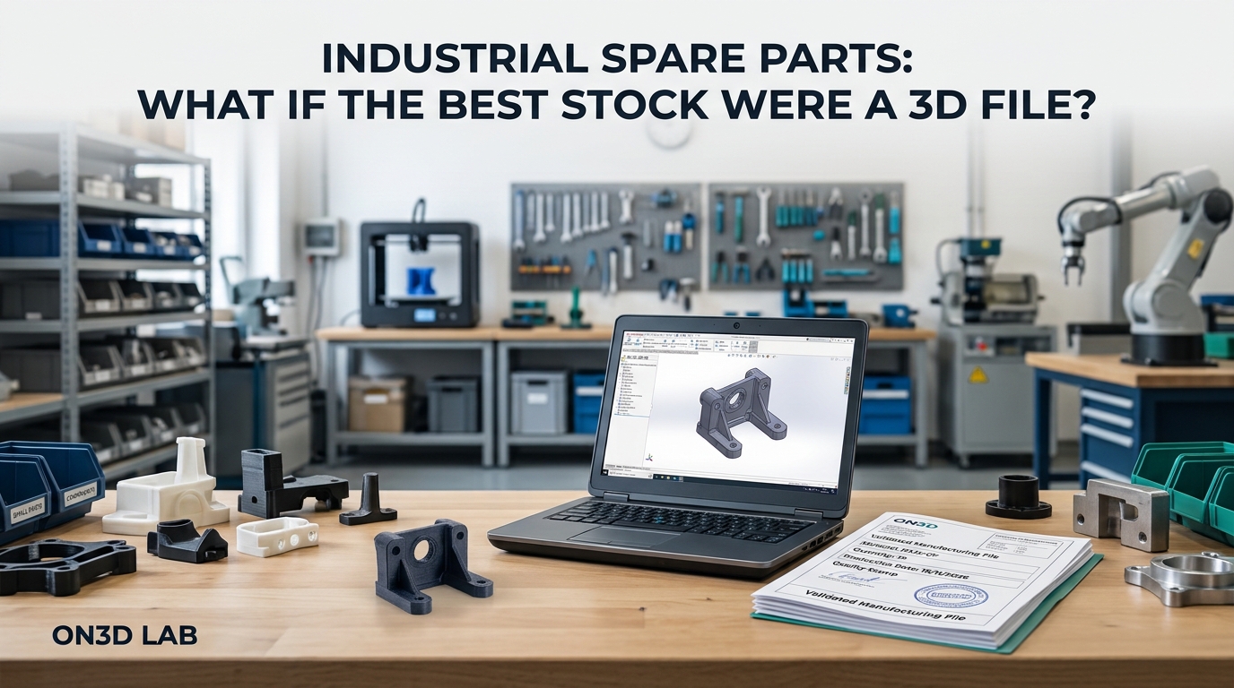
Some plastic parts are better retained as validated manufacturing dossiers than as dormant stock. Methods, examples and limitations.
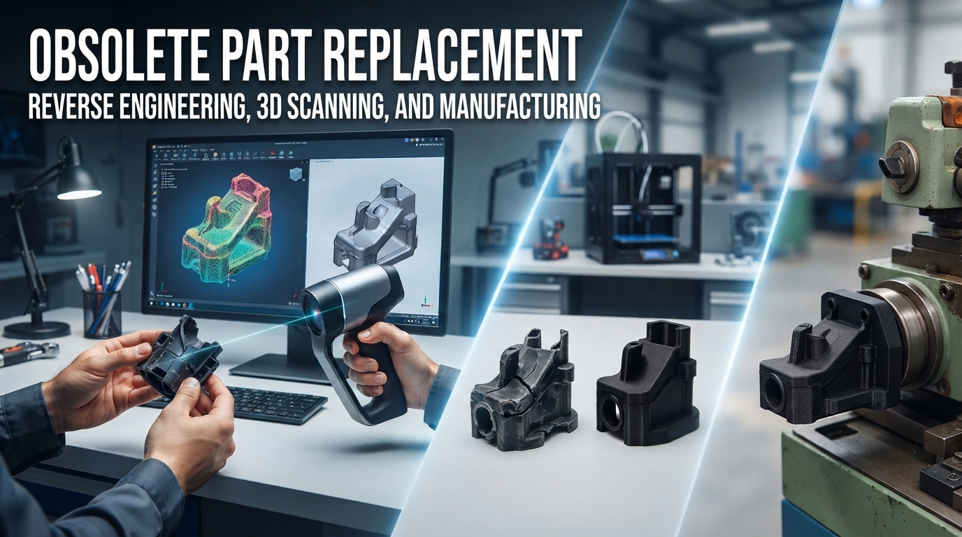
An unavailable plastic part can sometimes be rebuilt from an existing sample. Follow the steps from scanning to CAD, manufacturing and inspection, and understand their limits.